

Troubleshooting guide
Your Furnace Sequence of Operation
Understanding How Your Gas Furnace Starts and Runs
Prepared by
Bayne L. Vardy — BC Furnace & Air Conditioning Ltd. Serving Greater Vancouver homeowners since 1983.
Updated
The short answer
A gas furnace runs seven interlocked steps: thermostat call, inducer, pressure switch, ignitor warm-up, gas valve and burners, flame proving, blower. Each step is gated by a safety device, so the burners cannot light until the step before it has proved itself.
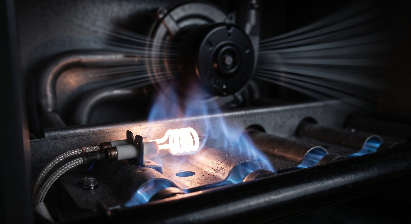
Knowing the standard sequence of operation of your gas furnace is important. It helps you understand what is happening when your heating system turns on, recognize normal operation, and better communicate with a technician if something does not sound or feel right.
Modern gas furnaces follow a carefully controlled, safety-focused sequence managed by the furnace control board. While exact timings vary by manufacturer and model, the steps below reflect the typical process for residential furnaces that use a hot surface ignitor (HSI).

01Thermostat Calls for Heat
When the thermostat is set to Heat and the room temperature drops below the setpoint, it closes the R-to-W circuit. This sends a 24-volt signal to the furnace control board. The board first checks that all safety components are in their correct positions (for example, limit switches closed and the pressure switch open) before beginning a heat cycle.
02Inducer Motor Starts
Once the safeties check out, the control board sends 120-volt power to the inducer (draft motor). The inducer begins running to clear residual gases from the heat exchanger and establish proper draft through the venting system.
03Pressure Switch Closes
When the inducer reaches its required speed and creates the necessary negative pressure, the pressure switch closes. This proves that the vent path is clear and the inducer is working properly. The closed pressure switch signals the control board that it is safe to proceed with ignition.
04Hot Surface Ignitor Warms Up
The control board sends power to the hot surface ignitor (HSI). Most systems use 120 volts, although some models use 24 volts. The ignitor glows for a timed warm-up period — commonly around 17 seconds, though the exact time can range from roughly 10 to 30 seconds depending on the furnace make and model.
05Gas Valve Opens and Burners Ignite
After the warm-up period, the control board typically cuts power to the hot surface ignitor and simultaneously sends 24 volts to the gas control valve, causing it to open. Gas flows to the burners and ignites on contact with the hot surface. All burners should light in a smooth, even pattern.
06Flame Sensor Confirms Flame
The flame sensor rod detects the presence of flame through a process called flame rectification and sends a signal back to the control board. This confirms that ignition was successful and that it is safe to keep the gas valve open. If flame is not proven within a short trial window, the board will close the gas valve and may attempt the sequence again or lock out for safety.
07Blower Motor Starts
Once the flame has been established for the amount of time programmed by the manufacturer (allowing the heat exchanger to warm up), the control board energizes the indoor blower motor. Warm air then begins circulating through the home's duct system. The blower typically remains on until the thermostat is satisfied and a short off-delay has completed.
Why This Sequence Matters
Each step is interlocked with safety devices. The furnace will not light the burners unless the inducer is running and the pressure switch has closed. It will not keep the gas valve open unless the flame sensor proves a flame is present. These layers of protection help prevent unsafe conditions such as unburned gas accumulating or improper venting of combustion byproducts.
Understanding the normal sequence also makes it easier to notice when something is off — such as the inducer running but no ignition occurring, repeated clicking or lockout codes, or the blower starting unusually early or late.
Important Notes
- Exact timings (pre-purge, ignitor warm-up, blower-on delay, post-purge) vary by brand and model. Always refer to the manufacturer's documentation for your specific furnace when precise values are needed.
- Some furnaces use direct spark ignition instead of a hot surface ignitor; the overall logic remains similar, but the ignition step differs.
- If your furnace is not completing the sequence as described, or if it is displaying error codes or locking out, contact a licensed technician for diagnosis and repair.
Do not skip this
Never bypass safety switches or pressure switches. These devices exist to protect the home and its occupants.
Common questions
- How long should the hot surface ignitor glow before the gas valve opens?
- Commonly around 17 seconds, though the timed warm-up ranges from roughly 10 to 30 seconds depending on the make and model. After the warm-up the board typically cuts power to the ignitor and sends 24 volts to the gas valve at the same moment.
- Why does the blower start well after the burners light?
- The board waits for the flame to be established for a period programmed by the manufacturer, which lets the heat exchanger warm up first. It then energizes the indoor blower, and typically keeps it running through a short off-delay after the thermostat is satisfied.
- What voltage does each stage of the sequence use?
- The thermostat call is a 24-volt signal on the R-to-W circuit. The inducer runs on 120 volts. The hot surface ignitor is usually 120 volts, though some models use 24. The gas valve is opened by 24 volts from the control board.
Parts in this guide
Read next
Know which part failed? We ship it.
Ignitors, pressure switches, control boards and gas valves on the shelf at our Coquitlam warehouse — same-day pickup in Greater Vancouver, shipped worldwide. Call with your model number and we will confirm the part before you order.